Hey everyone,
I'm making a project with a DIY-microcontrollerboard. The structure is as follows:
1. LabVIEW generates the data which should be sent
2. This is sent through the USB-port using the VI's provided by FTDI
3. FT232R receives the USB-data and translates it to UART-data
4. UART-data is sent to the PIC16F726 which basically forwards this data to the SPI-port
5. Received UART-data is converted to SPI-data and sent to the LMP90100 eval-kit
Now the data communication between PIC & LabVIEW works fine. I've tested this lots of times before and I have multiple screencaps of the Logic Analyzer interpreting the data. I will add a screenshot ASAP.
In the research phase before, I had connected the SPIO-4 board to the Eval Kit and I used the logic analyzer to take a look at the data-transfer. This is when I found out that the SPIO-4-board sends all data in groups of 2 and so I have done the same with my project. What I would like to do is first of all initialize the Eval kit by sending all the necessary settings for my measurement and second of all I would like to make an ADC-reading of this.
The first command I send is the following 4 byte sequence:
0x10 - 0x01 - 0x02 - 0x05
This should write data-byte 0x05 to address-byte 0x12 meaning activating the current source and letting 500µA flow through it. However, the current source doesn't activate and the resistor I placed over the current source doesn't have a voltage when measured. I'd really appreciate it if I could get some feedback on this matter.
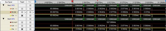
The lines of PIC-IN & PIC-OUT are switched out. The visible data is sent by the PIC, not received. Data-packets can be read in Communications.txt
(Please visit the site to view this file)